
Functions Overview
 LOYTEC offers a wide range of products for various applications in building automation. Those application-centric products often combine an entire set of different functions on one single device (L-INX Automation Servers, IP-capable L-IOB I/O Modules and Controllers, L-ROC Room Controllers, L-GATE Gateways, L-VIS Touch Panels). This enables a given product to be used for different tasks. For example, the L-GATE as a typical gateway also has the ability to host a graphical user interface to dynamically visualize a site or record historic data in trend logs. L-INX Automation Servers are primarily programmable controllers but can also be used as gateways depending on the available protocols.
We have high quality standards in research, development, and production of our products. In order to offer the same high standards to our customers, the programmable controllers may only be purchased by trained staff of companies that are enrolled in the LOYTEC Competence Partner Program.
For all functions, LOYTEC ensures common workflows for configuration and operation. The workflow for configuration of certain functions is the same, regardless which device is used. This applies for integration in different communication network technologies, creating schedules, alarm conditions, trend logs, and even for the design of graphical projects. For an efficient workflow the user can — depending on the network technology — create single data points or entire device templates via a network scan or file import. The use of a single configuration tool for a range of product models such as the L-INX Automation Servers, L-IOB I/O Modules, L-IOB I/O Controllers, and L-GATE Gateways, reduces the learning curve notably when working with LOYTEC products.
The combination of different functions on a single device and the common workflows for configuration and operation offer a maximum of flexibility when selecting LOYTEC products for various application requirements. On the following pages we give an overview on the offered functions. For more detailed information on the presented functions please refer to the respective product manuals, which are available for download on our web site. The functions are represented by symbols, which are referred to by the respective product descriptions later in the product's description.
 On a LOYTEC device it is possible to define alarm conditions for each data point. This can be done independently of the underlying communication technology (CEA-709, BACnet, DALI, M-Bus, Modbus, KNX, etc.) or the underlying, physical data point of a L-IOB I/O Module.


 The Internet of Things has brought forward an off-spring of devices with Web-based interfaces, such as Multimedia projectors, A/V systems, Smart-TVs, or smart light bulbs. LOYTEC’s groundbreaking JavaScript-based IoT integration allows to integrate them all. In short: If you can control it via app, you can integrate it into the building automation system or touch panel interface.
 The integrated e-mail client allows for the transmission of messages based on a timely basis or triggered by events. Message texts can be multi-line and consist of static text and variable placeholders, which are evaluated at the time of transmission and insert values into the text. Furthermore, alarm logs and trend logs can be automatically transmitted as e-mail attachments in CSV file format.
 Ethernet summarizes a variety of networking technologies, software (protocols) and hardware (cable, hubs, interface cards, etc.) for wired, local area networks (LANs). Originally published in 1983 as the IEEE 802.3 standard, Ethernet has evolved to today’s most used LAN technology. As a packet-switched network, Ethernet belongs to the layers 1 and 2 of the ISO/OSI layer model and defines addressing and media access. Ethernet is a common basis for networking protocols such as TCP/IP and UDP/IP and is able to multiplex several application protocols at the same time (e.g. HTTP, FTP, IP-852, BACnet/IP, KNXnet/IP).
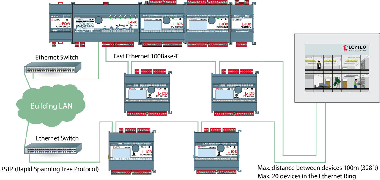
 An integral part of the LOYTEC hardware is a configurable firewall, which can be enabled and configured over the built-in web server, over OPC XML‑DA, or OPC UA. The built-in web server is accessed via the secure HTTPS protocol. A pre-installed certificate allows a quick setup and can later be replaced by a locally generated certificate or by a certificate issued by a certification authority. Data communication is encrypted by TLS encryption methods. The use of secure certificates prevents man-in-the-middle attacks. Furthermore, the OPC UA server provides a secure alternative to OPC XML‑DA. It uses the installed server certificate and authorizes OPC clients by certificates.
 A BACnet Operator Workstation is designed to provide an operator with all the information and editing ability needed for managing a system on a daily basis. In addition to viewing and editing selected BACnet object, an Operator Workstation can display trends, schedules, and other specialized objects. It can also display reports and graphics. A BACnet Operator Workstation will notify the operator that an alarm has occurred, lets the operator acknowledge the alarm, provides a summary of alarms, and allows to adjust the alarm thresholds of analog objects.
") By the end of the 1990s, LON (Local Operating Network) was standardized by the Consumer Electronics Association (CEA) under the title “Control Network Protocol” as CEA-709. Today, the CEA-709 protocol is a recognized international communication standard, namely ISO/IEC 14908. LOYTEC is highly experienced in the CEA-709 technology. LOYTEC developed its own technology to make devices talk on CEA-709 networks. LOYTEC technology includes chip sets and also the fully featured ORION Protocol stack which executes the CEA-709 protocol on powerful 32-bit micro controllers. All LOYTEC devices supporting CEA-709 connectivity make use of this powerful technology. Communication Objects (Network Variables) and functional profiles, standardized by LonMark International (www.LonMark.org), describe the communication interface of a LonMark device. Configuration properties (CPs) allow downloading and modification of device parameters. Network integration is accomplished by a network management tool, which is independent of the hardware manufacturer (e.g. NL220 or LonMaker) and is used for device installation and creation of bindings between network variables, which are stored in a database. This allows for a clear separation between the application and the communication relations in the network. Configuration tools specific to LonMark nodes integrate as plug-ins into the network management tool and allow for fast and simple device configuration.
By the end of the 1990s, LON (Local Operating Network) was standardized by the Consumer Electronics Association (CEA) under the title “Control Network Protocol” as CEA-709. Today, the CEA-709 protocol is a recognized international communication standard, namely ISO/IEC 14908. LOYTEC is highly experienced in the CEA-709 technology. LOYTEC developed its own technology to make devices talk on CEA-709 networks. LOYTEC technology includes chip sets and also the fully featured ORION Protocol stack which executes the CEA-709 protocol on powerful 32-bit micro controllers. All LOYTEC devices supporting CEA-709 connectivity make use of this powerful technology. Communication Objects (Network Variables) and functional profiles, standardized by LonMark International (www.LonMark.org), describe the communication interface of a LonMark device. Configuration properties (CPs) allow downloading and modification of device parameters. Network integration is accomplished by a network management tool, which is independent of the hardware manufacturer (e.g. NL220 or LonMaker) and is used for device installation and creation of bindings between network variables, which are stored in a database. This allows for a clear separation between the application and the communication relations in the network. Configuration tools specific to LonMark nodes integrate as plug-ins into the network management tool and allow for fast and simple device configuration.")
") The newer DALI-2 standard also covers switches, multi-sensors, bus power supplies, and control systems in addition to luminaires or ECGs. DALI-2 devices must be certified by the Digital Illumination Interface Alliance (DiiA) to be entitled to carry the DALI-2 logo.The DALI-2 certification promises significantly improved interoperability and additional functionality compared to older DALI systems on the market (version 1). LOYTEC recommends to use preferably DALI-2 certified devices. DALI and DALI-2 devices can be used simultaneously within one DALI channel.
The newer DALI-2 standard also covers switches, multi-sensors, bus power supplies, and control systems in addition to luminaires or ECGs. DALI-2 devices must be certified by the Digital Illumination Interface Alliance (DiiA) to be entitled to carry the DALI-2 logo.The DALI-2 certification promises significantly improved interoperability and additional functionality compared to older DALI systems on the market (version 1). LOYTEC recommends to use preferably DALI-2 certified devices. DALI and DALI-2 devices can be used simultaneously within one DALI channel. EnOcean is a radio protocol for wireless products in building automation and is defined in the international standard ISO/IEC 14543‑3‑10. Switches, like sensors with EnOcean technology just need little energy for sending short radio signals. The energy is mainly produced from piezoelectricity during switching (energy harvesting), the energy of solar panels, or Peltier elements. This energy is sufficient for a batteryless, hence maintenance free operation of the sender. The wireless protocol is geared to transfer information energy efficiently yet highly reliable. Frequency bands with regional differences are used. Europe: 868.3 MHz, US/Canada: 902 MHz (also 315 MHz), and Japan: 928 MHz.
")

 The MP-Bus controls HVAC actuators for dampers, regulator valves or VAV air volume controls. It is a master/slave bus developed by Belimo ®. There are no restrictions with respect to network topology. Permissible topologies include star, ring, tree and mixed configurations. The MP-Bus (multi point bus) consists of three conductors 24 V (AC or DC), GND and the MP data line.
 The Standard Motor Interface (SMI) is a bus protocol used to control SMI sunblind motors for shading. On closer examination, the SMI is a digital interface with the benefit to parallelize the connection of roller shutters and sun protection drives. Furthermore, the automation controller gets feedback from the drives and the possibility of flexible parameterization. This allows telegrams to be exchanged over the consistent interface, from the controller to the drive and vice versa. SMI drives from different manufacturers are compatible with each other. For drives that operate on mains voltage, the drive and controller are connected by a 5-core cable which both supplies power and transmits data. Distances of even up to 350 m between the controller and drive are possible. Up to 16 drives per SMI channel can be connected in parallel. In this way, the hardware expense is reduced significantly in comparison with today's conventional technology. Even when connected in parallel, the drive status can be queried by the sun protection controller.
 The OPC server on LOYTEC devices, which support security, also features the OPC UA binary protocol, that exposes the same OPC tags as the OPC XML-DA server. More details on OPC communication can be found in the respective product manuals, which are available on download.
 LOYTEC devices offer remote access functions, which differ depending on the device model. All device settings can be modified, data point values can be queried, and configuration parameters can be modified. Apart from this, backup and restore of the device configuration is available. The same applies to parameters. Access to AST™ functions for alarming (alarm management), scheduling, and trending (historic data recording) is also supported, including reading out alarm logs and trend logs from the device via file transfer. The devices offer various analysis functions and statistical data for troubleshooting the used communication protocols. Programmable LOYTEC devices also provide online test functions for developing application programs.
 WLAN refers to a local wireless radio network compliant to the common Standard IEEE 802.11. It extends all protocols of the wired Ethernet of corresponding LOYTEC devices to a wireless communication.
 The LTE function refers to supporting mobile communication standards for LTE, UMTS/HSPA+ and GSM/GPRS/EDGE. It is approved for :
 Bluetooth is a wireless communication technology in the UHF-range from 2.402-2.480 GHz. The IEEE standardized Bluetooth in IEEE 802.15.1, but no longer maintains the standard. Instead, the Bluetooth SIG oversees development, specification, qualification program and protects the trademarks. An important boost came with the introduction of Bluetooth Low Energy (BLE) as a subset of the Bluetooth v4.0 core specification. The entirely new protocol stack for rapid build-up of simple links is aimed at very low power coin-cell applications such as advertising beacons for indoor navigation and asset tracking.
 In 2017 the Bluetooth SIG introduced Bluetooth Mesh on top of the Bluetooth v4.2 specification. In difference to classical Bluetooth and BLE, the new technology allows many-to-many communication by using advertising channels only. It is based on a forwarding mechanism (relay-function) and a publish/subscribe method for data exchange. In difference to BLE Bluetooth Mesh is not limited by the direct connection range. In 2023 a reworked version (called “Mesh 1.1”) has been released by the Bluetooth SIG adding Mesh Protocol improvements like Directed Forwarding and Remote Provisioning as well as completely new specifications for Mesh Device Firmware Updates and Mesh Network Lighting Control Profiles.
 A "local connection" is used for connecting data points of different networking technologies, which are integrated on a single LOYTEC device.
 "Global connections" provide similar functions as local connections, but can span across an IP network between two or more LOYTEC devices. A global connection creates a data cloud with a system-wide name. Data points which are added to a global connection can send values into the cloud or receive values from the cloud. This is entirely independent from the installation location or the original communication technology.
 The LIOB-Connect port of a L-INX or L-ROC device allows connecting LIOB-10x Modules and provides a power and communication path without additional cabling. Regardless of the L-IOB type, up to 24 L-IOB I/O Modules are supported. This makes up to 24 LIOB-10x devices possible in a daisy chain. The first four LIOB-10x can be connected directly. Starting with the fourth LIOB-10x, the LIOB-Connect chain needs to be divided into two (or more) segments using LIOB-A4 and LIOB-A5 adapters.
 The LIOB-FT port allows operation of remote LIOB-15x Modules. These are connected by twisted pair cabling of up to 500 m length in free topology or more than 500 m in bus topology. The maximum number of supported LIOB-15x Modules depends on the L-INX Automation Server model, the L-IOB IP I/O Controller model, or the L-ROC Room Controller model.

 The development of an application program is done in the graphical programming environment L-LOGICAD (IEC 61131-3 standard), which offers programming languages using function blocks (FBs) or structured text (ST). It is possible to mix programming languages within the same project. The IEC 61131-3 programming software allows an online test of the application over the Ethernet/IP network or the TP/FT-10 channel (depending on the hardware). IEC 61131-3 applications can be modified without interrupting execution. L-LOGICAD offers a variety of tools for diagnosis and debugging, commissioning, and additional service function blocks (e.g., force update). Errors can be detected early when developing the function plan in the integrated, graphical offline simulation. Oscilloscope and logic analyzer functions allow a timely display of the respective values. Apart from this, watch pages can be added for visualization and modification of run-time values. L-LOGICAD can access all data points and parameters on the device and process them in the logic program. The program operates independently of the underlying communication technology or the underlying L-IOB I/O Module.
 The application project is created with the graphical programming system L-STUDIO (IEC 61499 standard), which allows programming using function blocks (FBs). In L-STUDIO, the programming environment comprises the entire project, where each controller in the IP network is treated as a computing resource with data points. L-STUDIO deploys the application to the networked controllers and creates the connections between them automatically. Event-oriented execution of the program allows for fast reaction times. As a novel approach to automation we name this "Cloud Control". An arbitrary set of functions can be mapped to a cloud of controllers. The strictly object oriented programming method allows for efficient reuse of previously implemented functions. A variety of debugging and watch functions allows for building-wide troubleshooting during run-time.
 L-STUDIO has established itself as an integration platform for the L-ROC system for individual room control installations. With the new version L-STUDIO 3.0, LOYTEC is now taking the next step and extending the programming function by a development environment in accordance with the industry standard IEC 61131.
 Math objects with user-defined formulas can execute mathematical functions on data points. A math object uses a number of data points as input variables (v1, v2, …, vn) and calculates a result according to the formula. The result is written as an output to a number of data points. The calculation is executed each time one of the input data points changes its value. A result is calculated only if all inputs have a valid value.
 Depending on the device model, there exist several possibilities to backup and restore a device configuration. In principle, all LOYTEC devices with a built-in web server offer the backup and restore function on the Web interface. Also the Configurator tools provide this function for their respective device models. When using the L-WEB System, backups of device configuration can be created on a timely basis (e.g. once a day) and restored easily when needed. Devices with SD card support and USB port allow a device backup onto external storage. In this case, the backup and restore function is operated locally on the LCD display. In all cases, the LOYTEC device is restored with all data points, dynamic NVs and bindings, BACnet server objects and client mappings, etc. The device appears again as commissioned and online and is fully functional in the network. In case an LNS-based tool is used, the LNS device needs to be replaced, which can be done at a later time.
 LWEB‑900 gives a clear overview of the status of all devices and provides detailed information for each device (e.g. device type, name, IP address, firmware version, configuration file, program file, etc.). A firmware update can be performed for individual devices or groups of devices. A backup feature ensures a regular backup of all relevant device configurations. If a defective device needs to be replaced, the configuration can be easily restored. Depending on the device hardware, the restore operation can be initiated either from the LCD UI of the device or from the LWEB‑900 Client.
 LWEB‑900 manages and configures all LOYTEC devices based on a central database. The required device configuration software can be opened directly in LWEB‑900 and the configuration files are stored in the data base.
 Each data point is uniquely identified by its name and path. With LWEB-900, you can define your own identification key schema and assign identification keys (IK) to each data point. The IK schema can be exported and imported into other LWEB-900 projects.
 The built-in SNMP server (Simple Network Management Protocol) provides network management information of a device that can be used by customary IT tools. Via a configurable SNMP agent, status information and statistics with standard MIBs (Management Information Bases), system registers, and all OPC-exposed data points can be read and monitored, and also alarms can be sent.
 The VNC (Virtual Network Computing) service offers password-protected remote access to the LOYTEC device. VNC employs a client/server model. The VNC server is a built-in component of the LOYTEC device. A great variety of free or commercial VNC clients is available on the market for different platforms. Which functions and views are exposed over VNC depends on the device.


 Graphical views are schematics that help to visualize and operate areas of a building. Each graphical view can consist of a large number of dynamic display elements which reflect the current status of the facilities. LWEB-900 provides the graphical view within the LWEB-900 User Interface of the software and additionally offers distributed LWEB-900 clients the same functionality of visualization through Web services.
 LWEB‑900 can create reports based on trend logs. Reports can be used, for example, to document the energy consumption in a building. The generation of a report can be triggered in one of the following ways:
 LWEB-900 provides a separate work environment for each user. A user has to log on to the system and is presented with a perspective tailored to his individual requirements. A perspective defines which windows are open and how they are arranged.
 The LWEB‑900 watch view allows observing data point values in real time. Depending on the data point types, the values can also be changed and easily edited within the watch view. You are able to see what is actually going on in the network.

 The L-STAT is a network thermostat with a modern, minimalistic look that fits any interior design. It is directly connected to a LOYTEC controller with a Modbus interface such as LIOB‑AIR or L‑ROC.